In a random outburst of generosity recently, a kind individual gifted to me an abandoned electronic drum kit, which has been particularly great as I would probably never have bought one otherwise.
This page summarises the learning experiences which have followed.
Chain of events
Pick up Alesis kit
I think I was possibly the third or fourth person to inherit this thing, because it is a weird combination of random hardware from different manufacturers, skillfully bodged together.
At its core though, it is mostly Alesis' "starter" DM6 kit with some Roland rack parts.
Determine that hardware is very good
Kick pedal has slightly weird bearings and general squeakiness, but not really much worse than any other reasonably priced new one would be.
Hi hat pedal is really solid, although the distance it travels before switching is somewhat excessive, and it's a bit wobbly on the way down too.
Determine that electronics are not so good
Sounds are a bit cheesy
Output is very noisy and crunchy (not the good kind)
No real MIDI support (only USB)
Hi hat pedal is only a digital sensor, open or closed with no half-closed states (which are my favourite).
Mess around with it for a while.
Despite these limitations, it was still a pretty acceptable solution for home practice without annoying everyone in the neighbourhood too much.
However, the final straw was the non-adjustable sensitivity, which combined poorly with my ongoing wish to specifically practice consistency in the softest techniques.
Attain motivation to purchase second-hand brain
(Yes, people call the sound generating module a brain)
I chose a Roland TD-4 -- similar connector, real MIDI, nice practice features, older but not too old.
Compatibility
In the 1970s/80s, I guess people were too busy making stuff work, and didn't have time to invent too many ways to make things difficult.
Drum modules were of course invented in this era, and in all but the most esoteric/expensive models, the interface is still really simple to this day. All the pads are just contact mics, and in the case of the DM6, the kick drum is just another good pad rather than any disappointing cheapo option.
As a result, it was just a case of connecting the new brain's wiring harness up to all the existing pads, and everything worked perfectly.
...except the hi hat pedal, which glitched constantly and in fact barely worked at all. A solution was going to be needed.
So how do they make one that works?
The brain uses a simple analogue input for the hi-hat pedal. It detects changing resistance between the tip and sleeve of the jack connector, and interprets this resistance as a measure of how "up" the pedal is.
But how to detect pressure and turn it into a resistance value?
Well I was imagining all sorts of hellish effort to physically adapt a strain gauge or whatever, but actually the answer is to just buy the right sensor, the type of sensor probably used in the original design that led to this interface in the first place.
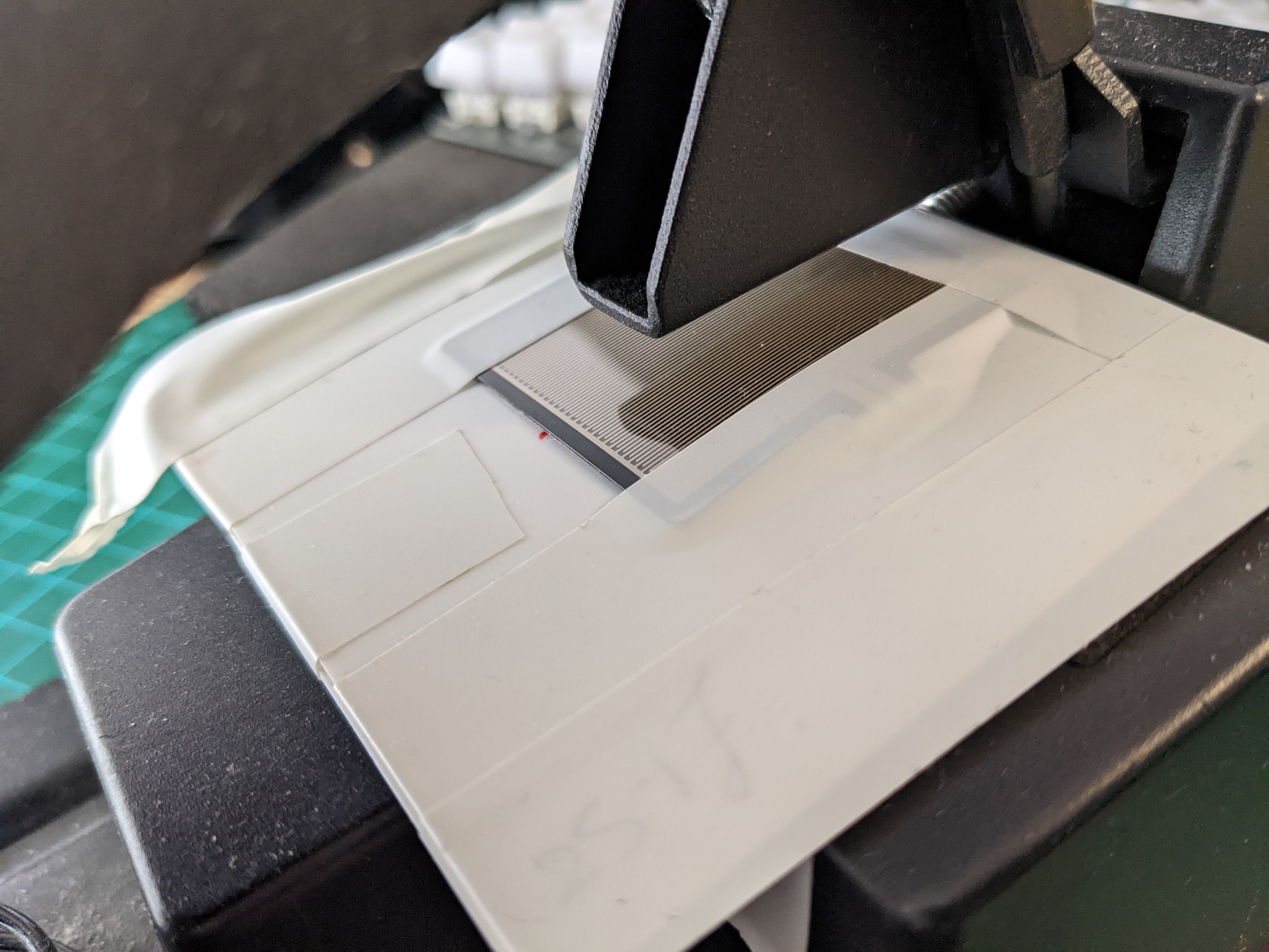
Here you can see the sensor in place beneath the little foot which touches it. It's a force sensing resistor (FSR), which seems to be basically some interleaved conductive layers with intentional weak separation that can be overcome by pressure.
These sensors are very easy to use in fact, they basically vary from infinite resistance when just placed on a surface, to a fairly variable few-hundred ohms when pressed down on hard.
They don't give particularly repeatable results (particularly if the pressure applied is in different shapes or varying positions), and would never replace a strain gauge in higher-accuracy situations, but in this application using only light-ish pressure, the sensor behaves extremely well.
Mechanical stuff
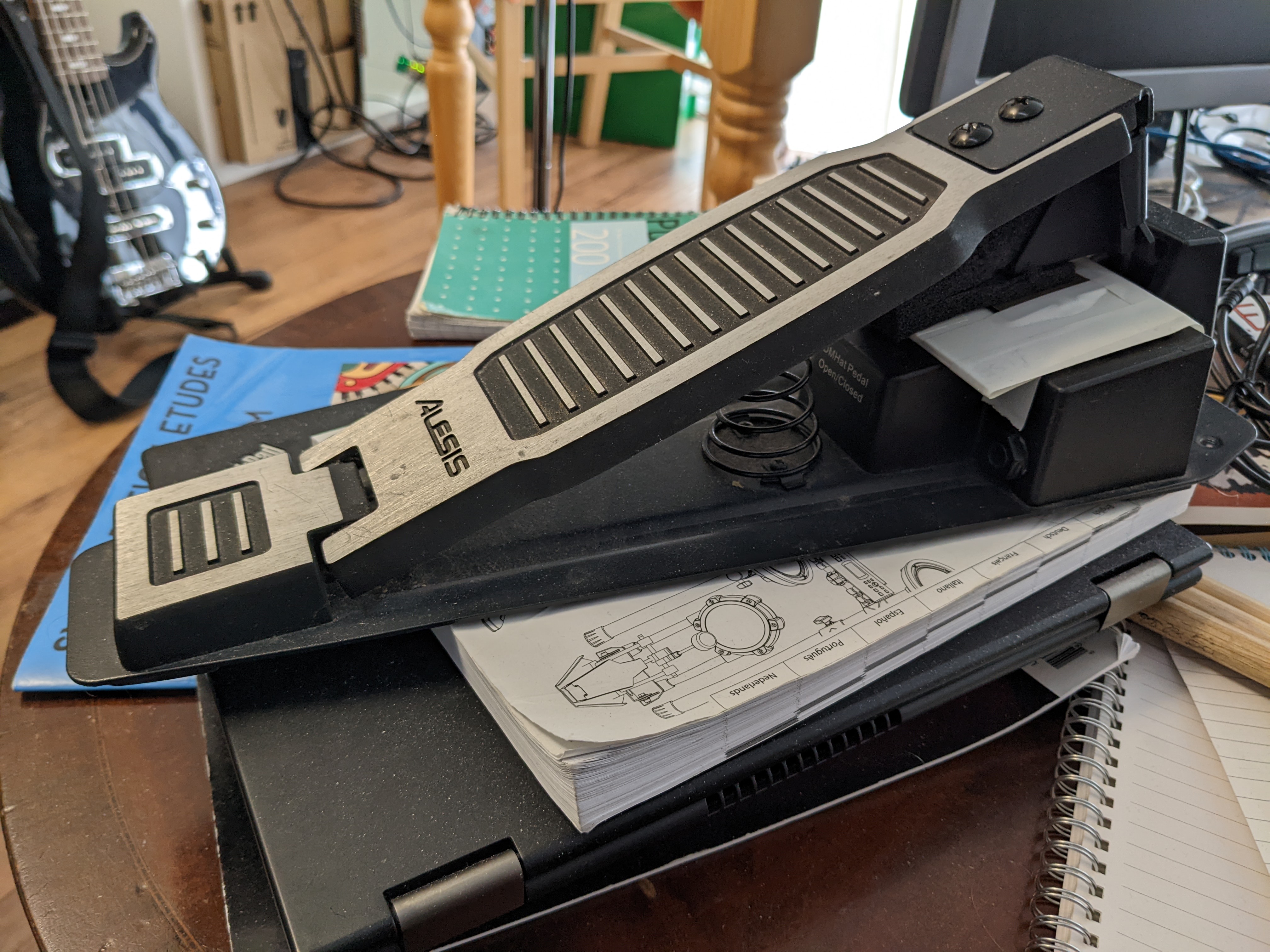
I haven't put a huge amount of effort into the final product, as you can see.
My more mechanically-skilled housemate kindly provided me with some 3mm styrene sheet, when I asked what he'd recommend for a stiff yet not-too-hard material. Two layers of this are placed beneath the FSR to provide a stable base and prevent nasty deformation, and the flexible "tail" that ends in the connector pins is passed through the sandwich via two slots, one just under the FSR's edge and one in the centre of the lower layer, into the pedal's original enclosure.
This is all held in place by good old electrical tape, which is fine in this case as everything is pretty happy with its placement and not wanting to shift.
A "carefully" shaped piece of foam is jammed in the little foot which sticks down beneath the footplate, reducing the travel before contact with the sensor and eliminating any sharp direct pressure from the powder-coated metal.
I gutted the original internals of the pedal, removing the original PCB which had the giant rubber dome switch and the jack connector, and screwed in a standard panel mount connector in its place. My own tiny circuit board which I needed for reasons you'll hear about shortly, was connected with flexible cable to the FSR and to the connector, and held in place with extremely adequate hot glue inside the original enclosure.
With only this relatively sturdy sandwich of plastic visible externally, nothing else sticking out to get disturbed, and the connector in the original location, the resulting unit more than meets my imaginary standard for robustness.
The only downside is that the pedal position in "closed"/down state is now at an oddly high angle -- but it's not too hard to get used to, arguably preferable to the original oddly low position, and makes up for itself with the extremely rigid and consistent feel of the resulting control.
Why the glitching?
During testing, even though the FSR itself provides a very smooth resistance curve if you look at it on a scope, it didn't behave too well when connected directly to the brain.
It turns out that possibly the original pedal was never "broken" in the first place -- the brain ignores the FSR too, if its resistance changes are too extreme!
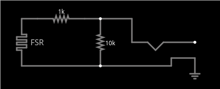
With the addition of a ~10k resistor across the output limiting the maximum resistance (stopping the circuit appearing open) and a ~1k resistor in line with one leg limiting the minimum resistance (stopping the circuit appearing short), the brain behaves a lot better. The full scale values seem to trigger some kind of fault detection and the pedal gets ignored, whereas with these limits in place things work a lot smoother.
The resistance values are an approximation and actual values were chosen by trial and error on breadboard between the pedal and the brain. The final circuit was just assembled on a tiny bit of protoboard, which seemed like the quickest way.
Knowing this solution, I possibly could have just added resistors in a cable between the Alesis pedal and the brain, and avoided the FSR entirely. Nonetheless, I'd still be missing out on analogue control if I'd done that -- and I'm actually very happy with this use of time, because the analogue feel of the resulting hack-job is literally perfect. I would, unusually, 100% recommend this kind of project.