One of the most consistent joys in life is the way that even (or maybe especially) a really mundane task can hold infinite depths of (potentially) interesting detail. If the task is pointless, this is somehow even better.
I generally don't enjoy having technology around for its own sake (probably because of too much time working on software) but do enjoy the mild sensory extravagance of having a proper stereo, and the stress reduction of having a home server for easy backups, basic network services and remote access. In this case it's a NAD C350 amplifier which has a decent number of inputs to connect to various things, and a Raspberry Pi 2 with a couple of USB hard drives attached. Both are, to my continual relief, totally adequate.
Adequacy
When I describe something as "adequate", this is a good thing. It means the thing is actually good enough for its intended purpose, which means it is ideal. People often read it with a weird connotation of being "only just" adequate, but this makes no sense. Adequate is the opposite of inadequate. Anything "better than adequate" would be excessive.
In fact, things that are supposed to be excessive, for some reason, seem to normally end up being inadequate in some basic way.
In a whimsical evening of sickness several years ago, I managed to figure out (inefficiently and stupidly, but eductionally) how to remote-control the amplifier with software. This came in very handy when the (inadequate) infrared remote mysteriously and unrepairably failed shortly afterwards.
Control systems are only as good as the input they rely on. Like most software solutions, this remote control only works about 96% of the time. That's perfectly fine while I'm sat there with the bluetooth keyboard cursing and retrying, but when it's supposed to work unattended (as an alarm clock, for example)... it needs its own non-human feedback loop if it's going to be reliable.
Luckily, the only real unattended use case here is turning the power on and off, which is probably the only effect that's always easy to detect.
Noticing power
A weird extra feature on this amplifier is a "12v trigger output" which they intend you to use with other things' "12v trigger input"s to automatically power them on at the same time. I don't really know what the point of this is — I've never really seen anything outside a car with one of those inputs, except one ancient active subwoofer where it turned out not to work anyway. The manual doesn't specify how much current it can throw, so I don't know if it could drive a relay. I'm not even sure why it would be bothering to generate 12v, which would have to be specifically for this: the audio stuff almost definitely needs to run on a higher voltage than that; and most logic stuff, lower.
Nonetheless, it can definitely save me from having to open the case, if I can figure out a way of using it.
It's also hard to find detailed specs for the Raspberry Pi's GPIO pins (the input I want to somehow connect this to) but as that's a 3.3v device, it's quite unlikely it will be pleased to see the full 12v.
So, this output, 12v above ground when the amplifier is on, and unpowered when it isn't, needs converting into an output that is actually useful.
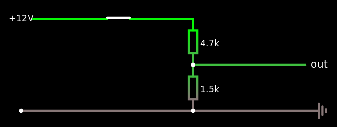
The simplest solution?
The simplest possible way to reduce a voltage is a potential divider.
We know the Raspberry Pi has 3.3v logic, so following the 2/3 rule of thumb we want at least 2.2v for a logic high, but not too much higher than that to be sure not to destroy any components. Assuming the input itself doesn't draw much current (which we know — by default they are passive high-impedance inputs) the divider should give us a pretty accurate result.
12v × 1.5kΩ ÷ (1.5kΩ + 4.7kΩ) = 2.9v
Seems adequate! This is actually a bit crap though.
I already have a general dislike of having to share a ground between equipment, especially in analogue audio world where it causes horrible noises to appear all over the place. Sadly that ship has already sailed here, with the "NAD link" connector for remote control already un-isolated.
But the most worrying thing is the general... sloppiness of the solution. In my opinion, having no idea where the 12v is derived from, it's irresponsible to directly use it. If a failure in the amp somehow leads it to fail up to the main DC supply voltage, which (bearing in mind it is running speaker outputs) could easily be at least 60v, it could destroy the server and then I'll have two ruined pieces of equipment instead of one. It could also turn out to be surprisingly badly regulated and cause problems by throwing sudden spikes (it looks stable with just a voltmeter, but as a voltmeter is a very stable load, this is a crap test — you never really know).
It's also irritating having to tailor the adaptor to just this specific voltage.
Is there a better way that's still reasonably cheap?
Of course there is.
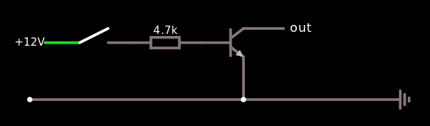
Output is for input
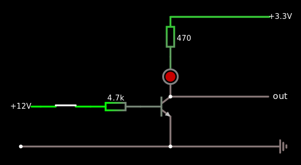
The "open collector" output is a traditional way of doing a single-ended output when it needs to allow for level conversion. The output consists of, literally, an open collector from a transistor.
A transistor is, effectively, a voltage-controlled switch [1]. This circuit means that the output doesn't carry any voltage at all any more [2]. Depending on whether the 12v is connected to the base or not, the collector output will either look like a short circuit to ground or, basically, a connection to nothing.
This abstraction seems weird at first, but converting the output to an open collector means that the connected device gets more of a choice over how to detect it.
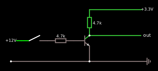
In this case, the easiest way to use the inputs we have is to have three leads to the Raspberry Pi. We will bring the Pi's own 3.3v supply over, via a resistor, to pull the input up to about 3v. When the output is activated, it will bring the input (second lead) down to the shared ground (third lead).
Because the transistor is very sensitive, we can use very resistant resistors, getting the right effect in terms of changing voltage while hardly wasting any current and therefore hardly consuming any power.
(The reason that 4.7k is a common number is, by itself, quite interesting).
It would also be possible to sacrifice efficiency to have an indicator LED, using a lower resistance to allow enough current to light it.
These diagrams are from one of the best web applications ever, Paul Falstad's Javascript circuit simulator. The green-ness indicates voltage (in a sort of logarithmic relationship). To see current, have a look at the simulation:
Semi-keen electronicists will notice that I'm using an old-fashioned junction transistor, not a FET. Why the hell would anyone do that these days?
Mostly, to be honest, because I already had some 2N3904s lying around, because they are cheap.
They are also easier to explain because they are simpler. GCSE electronics certainly didn't mention FETs, although that may just be because the syllabus was even more out of date than the computing one while I was still in school.
There could be one legitimate technical benefit as well, in that their simplicity, and typical relative chunkiness, makes them theoretically more robust against stray voltage.
The advantages of FETs, meanwhile, are basically speed, compactness and efficiency — and none of those matter here. In fact, speed is not all good, as it means more electrical noise... though of course that doesn't matter here either.
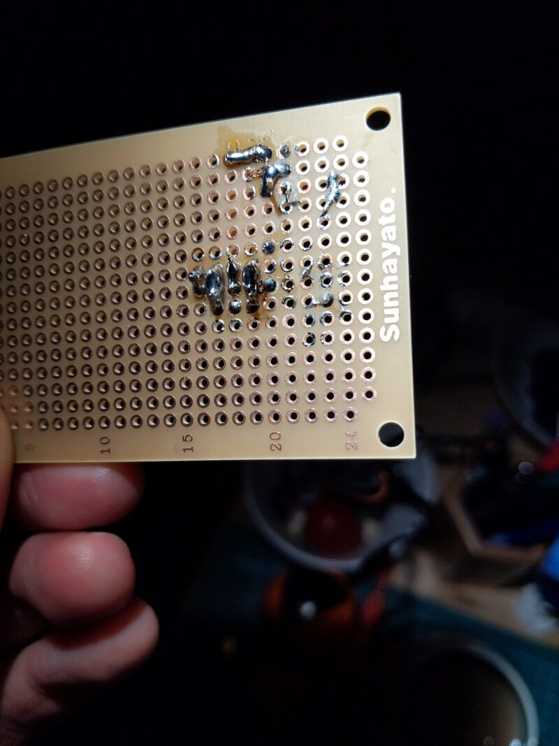
So, it works [3]. It's adequate. It's aesthetically terrible! Here's the protoboard[4] which the converter is built on. Connections are made with solder blobs between pins and I've used the unused pads to clean the iron. Who cares.
...unless the transistor fails closed, which will only happen if it accidentally gets about 100v, unless I'm very unlucky. The 4k7 resistor will also still be in there to limit the damage to about 2.5mA, which should keep things fairly unexciting.
Obviously, with this level of manufacturing quality, I wasn't stupid enough to connect it straight to the real equipment without testing it first. I first tested for shorts with a resistance meter, then used the Bus Pirate (which has a 3.3v supply with protection, a voltmeter mode and the same header pin connector as the Pi). A 9v battery stood in for the amplifier's output.
I wouldn't normally link to a product page, but I often use RS and this was one of the several things I had great difficulty finding on their site. While it's hard to search their site and they are almost never the cheapest supplier, they do have fast free delivery [edit: not free any more, sadly]. So, I left this link for my future self.